Timbre & Digital Nonlinear Waveshaping
Ask most modern modular synthesizer enthusiasts about the hallmark characteristics of Donald Buchla's instruments: no doubt, one of the first things they'll mention is the idea of a "complex oscillator." Today—generally speaking—the term "complex oscillator" refers to a general synthesis structure typically composed of two oscillators, a waveshaper, and various forms of inter-oscillator modulation. Typically, one oscillator is treated as a "primary" or “principal” oscillator, and the other as a "modulator." The primary oscillator's sine wave output is typically hardwired to the waveshaping section, which provides a series of controls for continuously altering the waveshape/sonic character of the sound. The modulator usually has the ability to modulate the primary oscillator's frequency, amplitude, and aspects of the waveshaping process.
Indeed, this structure was a key part of many of Buchla's instruments. Its beginnings can be seen in the dual oscillator designs of the 1960s Series 100 Modular Electronic Music System. The general approach to multi-parametric timbre control and hardwired inter-oscillator modulation appeared as early as 1973’s Stored Program Sound Source Model 208 (part of the now-famous Music Easel), and continued in the development of the 500 Series and later 200 Series modules. Perhaps most famously, this structure appears in the Programmable Complex Waveform Generator Model 259, which in recent years has become the conceptual inspiration for countless modern devices.

Detail of the Model 259 Programmable Complex Waveform Generator; from the 200 system at the University of Victoria, BC, Canada.
Many Buchla instruments—the 259 included—offer a continuously variable parameter called Timbre. In these instruments, the Timbre function is used to vary a specific aspect of a waveshaping process—usually, the amplitude of a sine wave prior to the waveshaper. Essentially, the waveshaping on, say, a 259 is a process by which a pre-wired sine wave from the principal oscillator is subjected to a fixed, nonlinear transformation process. When the sine wave exceeds a certain amplitude threshold, its curves appear to fold over on themselves; and as the amplitude of the sine increases, it is subjected to additional folding "stages," ultimately resulting in a complex, jagged, and harmonically-rich waveshape.
So, when the Timbre setting on a 259 is at its minimum value, for instance, a roughly sine-like wave is produced at the "final" output. As the Timbre value is increased, though, the sine wave is amplified, and the output waveshape gradually becomes more complex, resulting in a shifting balance of overtones. Moreover, the 259 facilitates internal modulation of the Timbre value via its dedicated modulation oscillator, resulting in continuously-shifted timbres and audio-rate timbral transformations. Continuous control of timbre is characteristic of most (if not all) of Donald Buchla's instruments, and this particular type of timbral transformation is considered by many to be a hallmark of his work.
Typically, definitions of the so-called "complex oscillator" concept are focused around the use of analog wave folding. And while certain versions of the original Music Easel, the subsequent 259, and other Buchla instruments did rely on analog shaping/distortion processes to effectively "fold" incoming sine waves, many other Buchla instruments continued this conceptual approach through different means. Instead of using analog wave folding processes, several later Buchla instruments instead utilized digital sound generation and a unique approach to nonlinear distortion/waveshaping…in turn, providing a different, yet similarly-parameterized approach to the continuous control of timbre.
In this post, we will outline some thoughts about the digital nonlinear distortion technique in Buchla's work. We will start with a brief, high-level explanation of conventional digital oscillator design. From there, we will define and provide context for the digital nonlinear distortion technique—including a brief discussion of its conceptual differences from wavetable synthesis (as these two techniques are sometimes confused with one another). We will then briefly discuss various implementations of digital waveshaping techniques in Donald Buchla's instruments.
How do Digital Oscillators Usually Work?
In the 1970s, computer-based sound generation was still a new field, and brought with it a number of practical constraints. Despite the increasing presence and power of computers (as well as newly-developed microprocessor technologies)—and despite the accumulating communal knowledge that surrounded them—digital sound generation required considerable computational resources. Academic musicians, acoustics researchers, and enterprising independent instrument designers constantly found and developed workarounds that enabled them to get the most out of the technologies available to them.
Digital nonlinear waveshaping—sometimes called nonlinear distortion synthesis—is one example of the many industrious approaches that researchers and instrument designers of the time employed. It offered an economical approach to the control of instrumental timbre, enabling continuous alteration of tone color and access to rudimentary forms of additive synthesis without the relatively computationally inefficient generation of many simultaneous, independent oscillators.
To better understand nonlinear waveshaping, though, we should first look at how waveshape—and thereby timbre—is more commonly defined in digital sound generators. The image below is borrowed from Max Mathews's 1969 text The Technology of Computer Music, and despite its age, it still offers a clear view of the general concepts of digital sound generation. We'll use this as a visual aid to specifically describe the behavior of a digital oscillator.

Simple graphical explanation of the nature of digital audio and digital-to-analog conversion from The Technology of Computer Music (Mathews, 1969).
Digital oscillators, samplers, and other sound generators often work by using a combination of an accumulation process and some form of digital memory. One can think of an accumulator as being a computer-based process that continuously counts—constantly incrementing its own value in order to create a conceptual "ramp." At any given moment, the current value of the accumulator can be assessed and used as a variable in any sort of process.
Digital memory typically involves the storage of many discrete states/values at specific "addresses." When reading values from memory, one would specify the address from which you would like to retrieve data. In a digital oscillator, an accumulator (or some derivative ramp-like structure) is typically used to determine that address—and the data at each individual memory address ultimately corresponds to the instantaneous amplitude of the outgoing signal. One can think of the stored data as representing many discrete amplitude values across a single cycle of a waveform. So, often, a digital oscillator uses a repetitive ramp/accumulation process to read these values in the same order, over and over, generating a stable, repeating waveform. By controlling the specific data at each address, one can define the specific waveform that the oscillator produces.
Of course, this overview is a bit simplistic, and there are many ways generate and control the counting function that is used to perform the memory lookup process. However, the key point for this part of our conversation is that, in a typical digital oscillator, an array of amplitude values is stored in memory and retrieved repetitively in a specific order, resulting in a constant and explicitly defined waveshape in the resulting sound.
This is a foundational concept in digital sound generation, and the basis of many derivative synthesis methods that have emerged in the ensuing 50+ years. But, for the sake of this conversation, let’s remember that one shortcoming of this technique as described is that the resulting waveshape is, again, constant. As such, many developments since have been aimed at, in one way or another, building on this basic idea while finding ways to make the waveshape variable—allowing for continuous timbral transformations as a means of musical expression.
What is Wavetable Synthesis?
We'll briefly digress here to address one such derivative technique: wavetable synthesis. While no known Buchla instrument uses wavetable synthesis per se, understanding how wavetable synthesis typically works will help to illuminate some of the idiosyncrasies of Buchla's digital oscillator designs.
In some situations, “wavetable” is the name given to the one-dimensional array of data that represents a wave shape (as described above)—it is, after all, essentially a table of values. However, “wavetable synthesis” co-opts this term and expands its meaning.
So-called wavetable synthesis (as implemented in popular instruments from PPG, Waldorf, and others) is directly derived from the technique described above; it simply expands on the concept by dividing the total waveform memory into smaller subsections, and allowing the user to dynamically change which portion of memory is used to define the shape at any given moment, even as the sound is being produced. In a sense, the waveform memory is treated like a “bank” of individual waveforms organized alongside one another: hence the term “wavetable” (quite literally, a table of waves).
Visual description of “Dynamic Spectral Wavetable Synthesis” from the user manual for the Waldorf Microwave—detailing the use of an envelope to “scan a Wavetable.”
One might consider the previously defined, static-timbre approach as using a "one-dimensional" waveshape addressing system (storing/retrieving a full, single set of amplitude values along a single axis). By extension, we can think of PPG-style wavetable synthesis as using a two-dimensional addressing scheme, treating overall waveshape selection as a secondary axis.
That is to say, we can think of individual amplitude values as being stored at specific X/Y coordinates in our “table”: the instantaneous position on one axis is determined by the accumulator/phasor, and the position on the other axis is determined by some "expressive," generally lower-frequency control source (an envelope, low frequency oscillator, detected key pressure, etc.). The resulting waveform depends on the moment-to-moment coordinate, as determined by these factors. Moving along the secondary axis (a parameter commonly referred to as Position) may result in the illusion of continuous/smooth timbral change, so long as the wavetable is composed of carefully-crafted waveshapes with subtle variations from one region of memory to the next. But, that extra dimension of control aside, the technique is effectively the same as the original "one-dimensional" concept described above.
While wavetable synthesis uses the same basic concepts and simply allows the user dynamic access to any of several stored waveforms, many other techniques develop on the basic memory-addressing-based sound generation concept in a different way: by manipulating the way in which the lookup function is performed. Think of it like this: the techniques we've described so far are based on "scanning" memory addresses using a linear ramp. But...what if you used something other than a ramp to perform the lookup process?
Digital Nonlinear Waveshaping
This fundamental concept—using a structure other than a ramp to "scan" a digital waveshape memory—is the basis of many now-standard synthesis techniques, including digital frequency modulation synthesis (a type of phase modulation), phase distortion, some subtypes of granular synthesis, etc.
This is also the basis of the nonlinear waveshaping/nonlinear distortion technique. Though this technique has not manifested in many commercial products, it was a popular topic amongst computer music researchers throughout the 1970s, as it provided a relatively economical means by which to define relatively complex timbres. Not only that—it could also, using only a small number of parameters, allow for the continuous evolution of timbre…an exciting prospect for the 1970s computer musician, indeed. At the time, it presented a promising alternative to techniques like John Chowning's frequency modulation synthesis, offering similar sonic potential through slightly different means.
Typical implementations of digital nonlinear waveshaping involve the use of a sine wave as the scanning function, effectively "scrubbing" or “scanning” the waveform memory back and forth in a repetitive fashion. When the sine wave is at its lowest potential instantaneous amplitude, the data in the first (lowest-numbered) memory address is retrieved; when the sine wave is at its highest instantaneous amplitude value, the data in last memory address is retrieved; when the sine wave is at its median value, the center-most address defines the outgoing amplitude. If we consider the memory addresses to form a conceptual X-axis and their resident data to form a conceptual Y-axis, the resulting audio waveform (plotted with time on the X-axis and amplitude on Y) will resemble a mirrored, slightly distorted version of the contents of the waveshape memory. The conceptual "shape" of the data being scanned may be referred to as the transfer function: a definition of how incoming amplitude values map to outgoing amplitude values.
It's important to remember that this is a form of waveshaping: using the amplitude of a signal as the driving parameter for determining its own level of distortion/alteration.
By using arbitrary data to define the contents of memory, this process can result in quite complex, harmonically rich tones; through the process of experimentation, one can begin to intuitively understand how different aspects of the transfer function (smoothness vs. discontinuity, axial symmetry vs. asymmetry, etc.) will manifest in the resulting sound. Arbitrary definition of transfer functions can certainly be rewarding, but there are also popular, somewhat-more-methodical approaches to nonlinear waveshaping that allow for more precisely predictable results.

Formulaic description of Chebyshev polynomials of the first kind 0–12; from Electronic Musical Tone Production by Nonlinear Waveshaping (Richard A. Schaefer, Journal of the Audio Engineering Society, Vol. 18 No. 4; July 1970).
One reason for the popularity of this method amongst 1970s computer musicians involves the use of a special class of mathematical functions called Chebyshev polynomials of the first kind (which, for the remainder of this post, I'll refer to simply as Chebyshev polynomials). Without diverging into the mathematical basis of these polynomials, we can summarize their usefulness in this context as such: essentially, Chebyshev polynomials allow for the formulaic construction of transfer functions that result in the production of specific overtones of a sine wave sent through the nonlinear distortion process.
That is to say that, for instance, defining the waveshaping transfer function by using a plot of the third Chebyshev polynomial will result in a sine wave three times the frequency of the input sine wave. Using the 17th Chebyshev polynomial will produce a sine wave 17 times the frequency of the input sine wave; and so on. What's more, defining the transfer function using a weighted average of the plots of multiple Chebyshev polynomials will result in an analogous amplitude balance of the corresponding harmonic overtones. As such, this waveshaping technique can be considered to provide a simple, efficient method of additive synthesis—producing highly predictable spectra, defined on a partial-by-partial basis, without the need for multiple oscillators. If all you need are exact harmonic overtones, this method is considerably more computationally efficient than summing together multiple independent oscillators. (Plus, as a bonus—the resulting overtones will always be perfectly phase-aligned, providing a certain consistent character/quality to the resulting sounds.)
Of course, this technique as we have described it thus far still results generally in output with a constant waveform/constant spectrum. By the mid to late 1970s, though, the technique had been exploited for more dynamic and peculiar results. In several research papers from the mid- to late 1970s (by researchers such as Daniel Arfib, Marc Le Brun, and others), this method is expanded through the addition of a signal multiplication stage prior to the shaping function. That is to say, by varying the amplitude of the sine wave prior to the shaping function, one can control the "width" with which the sine wave "scans" the memory. At a lower amplitude, the sine wave only scans indices toward the center of the shaping function; as the amplitude is increased, the "width" of scanning increases, and the sine wave accesses indices toward the table's extremities. One might think of this as a “scanning window” with variable width.

Two shaping diagrams from Marc Le Brun’s Digital Waveshaping Synthesis (Journal of the Audio Engineering Society, Vol. 27 No. 4; April 1979). The first of these diagrams details the result of a specific transfer function of a sine wave at varying amplitudes; the second uses MUSIC-N-style block notation to describe envelope-controlled waveshaping effects, in which a sine wave is multiplied by an envelope prior to a shaping function.
The sonic results depend heavily on the contents of the table used for the shaping function. Generally speaking, though, increasing the amplitude of the incoming sine wave will result in a relatively nonlinear evolution of the spectrum as a whole. That is to say, as the amplitude value increases, the yielded sound may exhibit a nonlinear timbral evolution in which certain harmonic partial tones seem to fade in and out independently of one another. Depending on the contents of the table, the resulting sound may shift generally toward emphasizing additional higher or lower-order harmonics as the amplitude of the incoming sine increases.
If the amplitude of the incoming sine wave is turned into a dynamic variable, one could use envelopes, LFOs, or other control structures in order to continuously vary the timbre of the resulting sound. The end results may be similar to opening a low pass filter in classic subtractive synthesis, or perhaps even more similar to increasing the index value in Chowning-style FM synthesis. It can be a quite evocative effect, and depending on the contents of the table used for the shaping function, may result in subtle or dramatic timbral changes.
In the 1978 paper Digital Synthesis of Complex Spectra by Means of Multiplication of Non Linear Distorted Sine Waves, researcher Daniel Arfib describes an implementation of this technique in which the incoming sine wave is multiplied not just by a static value or an envelope, but by another sine wave. By coupling this common technique (generic amplitude modulation) with the nonlinear distortion technique, a number of effects can result.
If one of the sine waves in question has a relatively low frequency (in the sub-audio range), the sound's spectrum will seem to evolve continuously, brightening and darkening over time. If both sine waves are running at audio rates at harmonically-related intervals, complex-yet-stable timbres result; if they are near harmonically-related intervals, the timbre may seem to evolve slowly (at a rate equivalent to the difference between the two oscillators' frequencies); if the two oscillators' frequencies are not harmonically related, the resulting sound can be quite spectrally complex and clangorous. That is to say that, using a relatively small number of variables, this technique can lend itself to the production of many distinct types of timbres.
Digital Nonlinear Waveshaping in Buchla Instruments
So, as discussed above, the now-famous Model 259 Programmable Complex Waveform Generator utilizes an analog nonlinear distortion process; the Timbre parameter controls the amplitude of the incoming sine wave through a series of essentially parallel simple nonlinearities, which are eventually summed to generate the effect of a more complex, multi-stage nonlinearity. The behavior of this circuit is often described as a type of "wavefolder.” (Note that Dr. Aaron Lanterman of the Georgia Institute of Technology has published a lecture to YouTube outlining this circuit's functionality, including an analysis of its spectral implications. Likewise, the 2017 paper Virtual Analog Buchla 259 Wavefolder—prepared by Fabián Esqueda, Henri Pöntynen, Vesa Välimäki of Aalto University and Julian D. Parker of Native Instruments GmbH for the 20th International Conference on Digital Audio Effects—offers a detailed description of the circuit’s behavior, complete with an analysis of its transfer function).

Model 259 Programmable Complex Waveform Generator (c. 1976).
The 259's internal modulation oscillator may, at the flick of a switch, be used to perform "Timbre Modulation"—effectively modulating the amplitude of the principal oscillator’s sine wave prior to the nonlinearity (similar to the techniques described by Arfib in the paper mentioned above). In the 259, the modulation source may be a saw, square, or triangle wave, providing many variations on this peculiar timbral effect. The concept of the Timbre control and Timbre Modulation was central to many of Donald Buchla's subsequent instruments.
The 259, though, was the last of his known oscillator designs to utilize analog waveshaping techniques until the introduction of the Model 261e Complex Waveform Generator in 2006. Produced in the interim, however, the Model 360 Programmable Octal Signal Source, Touché, 400, 700, and Model 259e all utilize the type of digital nonlinear waveshaping that we've been discussing. That being said, they each implement/parameterize it in a slightly different way—so, let's take a brief look at each. Don't fret...we'll come back to all of these in greater detail in the future.
The 360 and Touché (c. 1979–80, developed in collaboration with David Rosenboom) were the first completed Buchla instruments to utilize this waveshaping method. Both of these devices utilize the same internal sound-generating electronics—the 360 in the form of a two-panel-unit module for use in a 300 Series system, and the Touché in the form of a self-contained instrument with a black-and-white mechanical keyboard. Each of these instruments contains an eight-voice polyphonic sound generator, in which each voice contains three oscillators, two waveshapers, and one low pass gate. One oscillator for each voice acts as the principal (audio) oscillator, which ultimately passes along to the waveshapers; the other two oscillators are used to independently perform frequency modulation and timbre modulation of the primary oscillator, if desired. The waveshape produced by each oscillator is, invariably, a sine wave. Timbre modulation, in this case, corresponds to the technique described above in relation to Arfib's 1978 publication: effectively, the timbre modulation oscillator and principal oscillator are multiplied in order to dynamically scale the signal prior to the shaping function.

Model 360 Programmable Octal Signal Source (c. 1979).
In the Model 360 Programmable Octal Signal Source, the waveshaping section of each voice has two primary parameters: Low Order Timbre (LOT) and High Order Timbre (HOT). The LOT parameter corresponds to the concept described above, in which the amplitude of a sine wave is varied prior to the shaping function, effectively defining the "width" of the sine wave’s scanning “window” in the waveshape table. The HOT parameter performs a sort of blend between two selected waveshape tables, effectively allowing the user to crossfade between the output of the two shaping processes. Part of the 300 Series, the 360 is programmed using the PATCH-IV computer language. Users could select from a group of 16 built-in tables; but a sub-program called WSEDIT could be invoked in order to explicitly define custom shaping tables, as well. Tables were specified by entering up to 127 sets of X/Y coordinates for breakpoints. Note that there was no direct provision for graphical display of the shaping table—however, one could connect the output of the 360 to an oscilloscope for visual feedback of the programmed shapes, if desired.
The ability for the user to define the transfer function of the distortion process in this way is, if I may say so, a pretty mind-blowing concept. One can think of the digital waveshaping in these instruments as being similar to, say, the Timbre functionality of the all-analog 259; however, the transfer function of the 259's shaping circuitry is fixed/constant. In a sense, the WSEDIT functionality in the 360 enables users to define their own desired wave shaping behavior, rather than being stuck with a fixed shaping character.

Detail from the product brochure for the Buchla Touché (c. 1980).
The Touché functions somewhat similarly; but rather than using two shaping tables per voice, it utilizes only one (and instead provides the option for bi-timbral operation). As such, the LOT/HOT distinction is lost, and replaced with a single control for Timbre (along with controls for Timbre Modulation Frequency and Timbre Modulation Index). When initially developed, the Touché offered only a small pre-set selection of shaping tables; however, David Rosenboom (who authored the Touché's software) did eventually add an experimental facility for arbitrary table definition to his personal instrument.
This waveshaping concept was continued in the 400 (c. 1982). Unlike the 360 and Touché, the 400 is a six-voice instrument, in which each voice contains only two oscillators, a single waveshaper, a resonant low pass filter, and a VCA. As with earlier designs, one oscillator is treated as a principal (audio) oscillator, and is coupled directly to the waveshaper. The second oscillator may perform frequency modulation, timbre modulation, or both; a single modulation index control impacts the depth of modulation, even when both FM and TM are selected.

Buchla 400 - Midas II waveshape editor (c. 1982)
While the 400 provides only a single waveshaper per voice, and therefore no direct provision for crossfading between tables, it should be noted that the 400 is a fully multi-timbral instrument, and allows for the independent selection of shaping table and all other instrument parameters/settings on a per-voice basis. So, each voice could use the same general instrument parameters but have differing shaping tables; or, each voice could be programmed entirely independently.
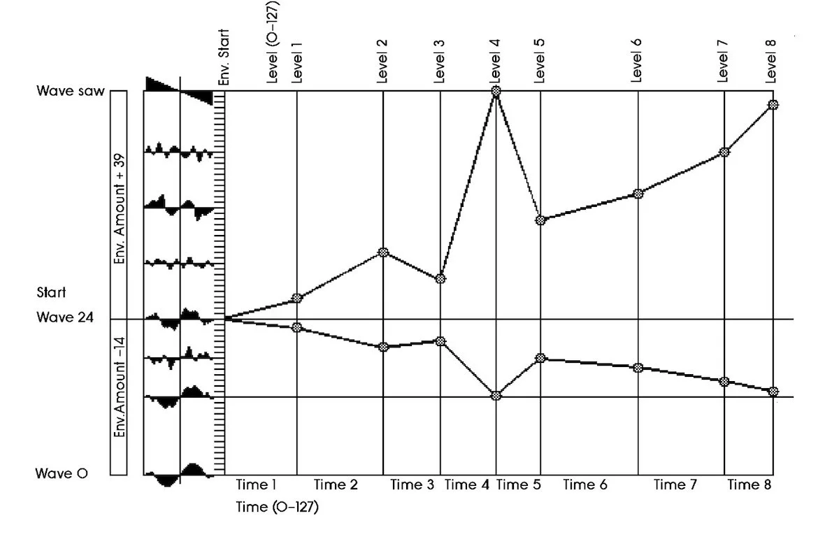
Happily, the 400—unlike the prior 360—replaced the text-based computer display with a graphical user interface, including graphical display and editing of the instrument's shaping tables. Early software "languages" for the 400 still only allowed for point-by-point definition of shaping tables (with the significant advantage of the graphical display). However, later versions of the 400 software also allowed for the definition of shaping tables using continuously variable Chebyshev coefficients (corresponding to harmonic partial tones 1–24). When using this input method, the shaping table would automatically populate with the shape required to produce the selected combination of harmonic partials when the Timbre value was at its maximum. This provided a considerably more expedient and efficient means of data entry.
The 700 (c. 1987) used a display and data entry method very similar to the 400, again offering the use of Chebyshev coefficients to specify the contents of shaping tables. New to the 700 were controls for “brush size/width” in the definition of shaping tables, altering the permissible divergence between one point in the function and the surrounding points. And, of course, the 700 also allowed point-by-point shaping table definition, either by manipulating points graphically or by specifying point number and corresponding value in a dedicated text field (though, as the user manual for the 700 notes, “We doubt that anyone would want to do this.”) As with the 400, the 700 was fully multi-timbral, and allowed for the independent selection of shaping tables for each voice.
However, the 700 used a different voice architecture than any of the previously discussed instruments. The 700 was a 12-voice instrument with four oscillators, two waveshapers, a resonant low pass filter, and a VCA for each voice. Each voice's oscillators and waveshapers could be arranged with any of 12 preset "Configurations"—a signal routing concept somewhat similar to the "Algorithm" concept in Yamaha's DX series synthesizers. A Configuration specified exactly how oscillators could be used to frequency modulate one another, as well as specifying the signal sources for the two per-voice waveshapers. Each shaper could use a different table from one another, and the index (amplitude scaling value) of the signal passing into each shaper could be defined independently (and, as with all of the instruments we've discussed, this amplitude scaling value could be modulated via envelope, incoming CV, expressive data from the built-in control surface, and more). In some configurations, the same oscillator is processed through each of the shapers; in some configurations, different oscillators (even several oscillators) may be routed to each shaper.
In this implementation, the parametric terms “Timbre” and “Timbre Modulation” are lost. They are replaced by the more generic “Index,” which describes signal multiplication level in many contexts. Each Configuration features six continuously variable Indices, which in turn specify—depending on the selected Configuration—the “Timbre” value (width of the waveshape scanning window), timbre modulation depth, and frequency modulation depth. So, despite the fact the term Timbre is absent in the 700’s synthesis structure, the same types of synthesis methods found in the 360, Touché, and 400 are still available.
Finally, in the early 2000s, the Model 259e Complex Waveform Generator resurrected the digital nonlinear distortion concept in the form of a single-panel-unit module for the then-new 200e system. The 259e, despite its name and some apparent functional overlap, sounds and behaves differently from the original Model 259. Though it is composed of two oscillators in a primary oscillator/modulation oscillator arrangement, the 259e is a completely digital oscillator—one which notoriously embraces digital artifacts such as aliasing as part of its sonic palette.

Detail of an original Buchla Complex Waveform Generator Model 259e (c. 2004).
Rather than using the analog waveshaping of the original 259, the 259e takes an approach that closely resembles the parameterization of a single voice of the 360. The principal oscillator sine wave is subjected to a waveshaping process with two user-selectable waveshaping tables (green and red). The Warp parameter (similar to the 360's Low Order Timbre) determines the width with which the sine scans the selected tables, while the Morph parameter (similar to the 360's High Order Timbre) performs a crossfade between the two selected tables. Warp and/or Morph can each be internally modulated using saw, square, or triangle shapes from the built-in modulation oscillator, or may be modulated via external control voltage sources.
Eventually, due to requests from collaborators and customers, Buchla designed the Model 261e Complex Waveform Generator, which used digital oscillators and an analog waveshaping section that much more closely resembles the original Model 259. When the 261e was introduced, the 259e’s production was briefly discontinued...but it was soon resurrected as the Model 259e Twisted Waveform Generator.
Though it used a nearly identical hardware design as found on the Model 259e Complex Waveform Generator, the Twisted 259e's shaping section dove even further into the peculiar potential of digital nonlinear waveshaping. Rather than simply providing the user with a pre-set selection of shaping tables (as in the original version of the 259e), the 259e Twisted Waveform Generator also enabled the use of the module's own internal memory to define the contents of the current shaping table(s). Users could employ the Memory Skew function to continuously offset the position in memory from which data was retrieved to define the tables. The results are often harsh, noisy, and rife with jitter and aliasing—ultimately, giving its sounds a surprising level of detail and nuance with relatively minimal user input required.
There is much more to be said about the 259e, its evolution, and the people who contributed to its design. As with the best of Donald Buchla's inventions, the casual user might listen to some of its tones and wonder how they could possibly be used "musically." Of course, to the right musician, that question can be a springboard leading toward the definition of new types of music and new meanings of “musicality.”
Morphing Perspectives
The 259e was Buchla's final completed oscillator design that utilized the digital nonlinear waveshaping/nonlinear distortion technique. Its peculiar hi-fi-yet-lo-fi sound and its distinct differences from the original 259 initially led to some confusion about its nature; however, we consider it both important and interesting to note that it fits into the evolution of Buchla's oscillator designs quite logically. Without understanding the 360, Touché, 400, and 700, the 259e might have seemed to come out of nowhere; but in fact, it was a logical outgrowth of techniques that Buchla had already explored for over 20 years by the time of its introduction.
And, as the 259e itself evolved, it clarified that there is still much to be learned and many as-of-yet-unheard sounds to be discovered from digital nonlinear waveshaping—a simple technique that got its start during computer music's infancy. Indeed, this technique is still useful and promising, and has not yet been as extensively explored as other digital synthesis techniques of its era (such as phase modulation, phase distortion, etc.).
The public’s increasing focus on the 259 and Music Easel over the last 10–15 years—prompted by the introduction of clones, modernized reproductions, and derivative designs in new formats—have indirectly placed a significant focus on Donald Buchla's 1970s analog implementations of continuous timbral control. But, if we look into the subsequent decades of his work, we can see that this technique quickly took a new form, and from c. 1980 onward, he and his collaborators focused heavily on digital advancements of the same general concepts. Though popular opinion might label the use of analog wave folding as being a definitively "Buchla" technique, more of his individual instrument designs used digital nonlinear waveshaping than the analog wave folding processes that have become so popular.
Eager for more information? In future writing, we'll take a closer look at all of these devices and techniques in greater detail. In order to advance our documentation of the Buchla 400 specifically, we'll soon follow up with a more detailed overview of its particular voice architecture.
-RG